
Circuit Diagrams with Q#
If you’ve been exploring quantum programming using Q#, you may have been thinking, “This language is great and so easy to use! But what about visual learners?”
I’m a software engineer in the Azure Quantum Development Kit team, and I’m very excited to share a new feature I’ve been working on: circuit visualization in Q#.
One of the neat things about Q# is that it gives you the ability to express quantum algorithms in a procedural language that’s reminiscent of classical programming languages such as C and Python. If you’re already a programmer, this way of thinking will be very intuitive to you, and you can get started with quantum computing right away (if you haven’t done so yet, check out our quantum katas).
However, this isn’t how many people learn about quantum computing today. If you flip through any quantum computing textbook, you’ll see that it’s conventional to think in terms of quantum circuits.
We wanted to bridge the gap between these two different modes of thinking.
Getting Started
If you open any Q# program in VS Code, you’ll notice a little “Circuit” CodeLens above the entry point declaration. When you click on that, your Q# program will be represented as a quantum circuit diagram.
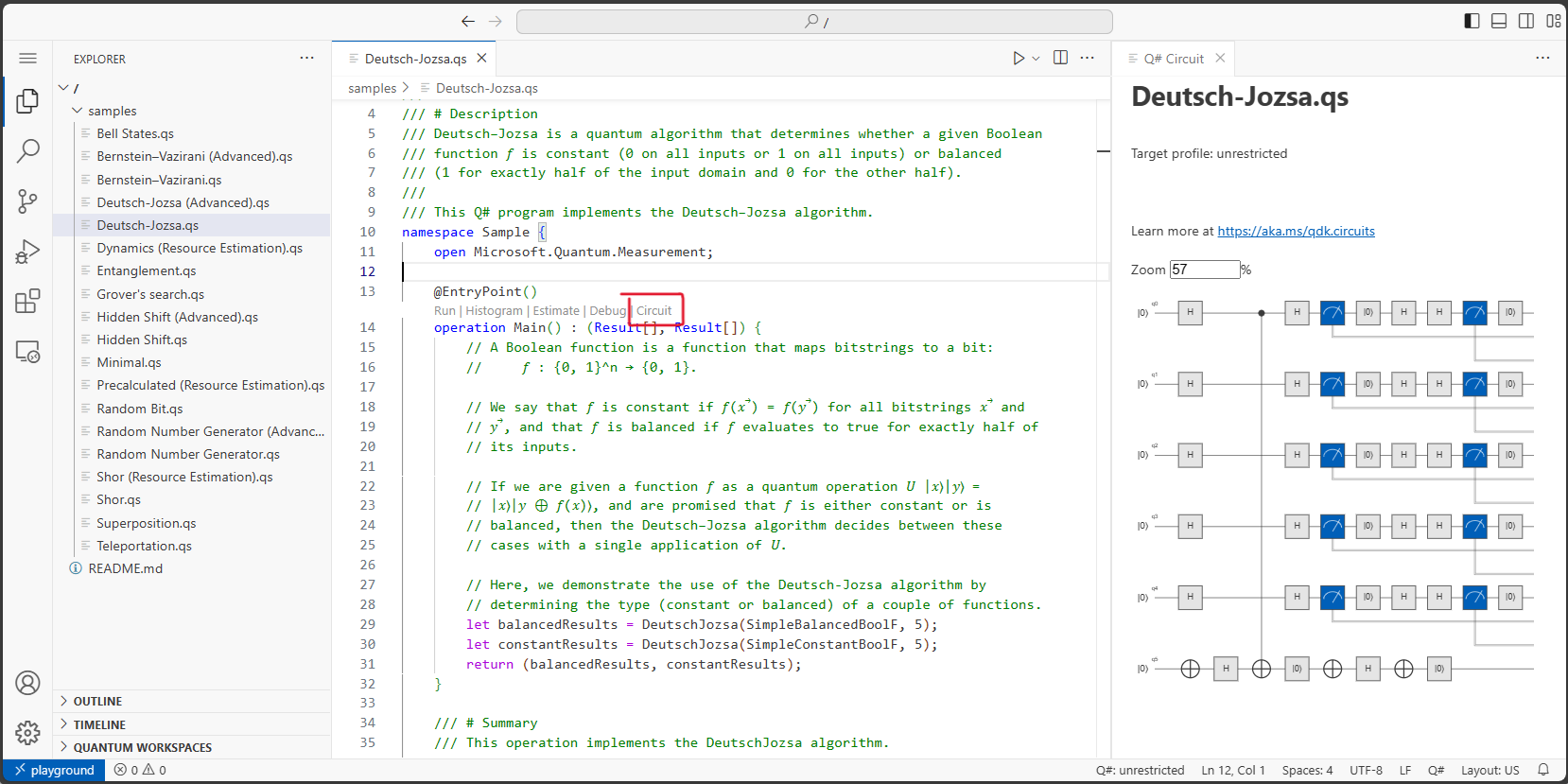
Being able to go from Q# code to circuit diagrams means that you can use familiar constructs such as for loops and if statements in your program to manipulate the quantum state while being able to view the logical circuit at any time to get a high-level view of your algorithm.

How does this work? The quantum circuit for a Q# program is generated by executing all the classical parts of the program while keeping track of when qubits are allocated and which quantum gates are applied. This data is then displayed as a quantum circuit.
Not all quantum programs can be represented as straightforward quantum circuits. What if we have a dynamic (commonly known as “adaptive”) circuit? Say we have a while loop in our program that compares measurement results and takes an action that depends on the result. The exact set of gates in the program will not be deterministic anymore.
That’s when we need to run the program through the quantum simulator. This is called “trace” mode since we’re tracing the quantum operations as they are actually performed in the simulator. When the circuit visualizer detects that the program contains measurement comparisons, this mode is activated.

Depending on your luck, you may end up with two gates, or you may end up with many more!
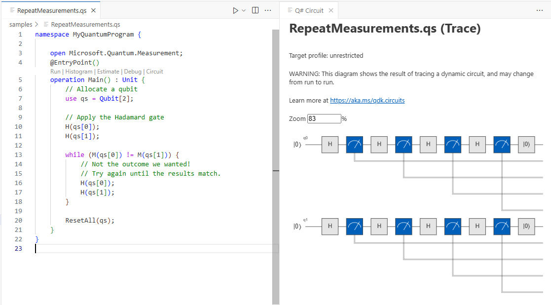
Each time you generate the circuit, you may see a different outcome in the circuit diagram.
It would certainly be nice to visualize all the outcomes at once, and we’re working through some ideas on how to do that. Simple conditionals can be represented as gates controlled by classical wires. But given a language as expressive as Q#, you can write complex conditionals that are difficult to visualize on a single 2-D circuit diagram. How would you represent an adaptive circuit such as the one above? We’d love to hear your ideas. You can leave a comment here or on this GitHub issue.
Reflections
Working on this feature sparked a lot of lively debate within the team, especially during the design stage. We’re a team with diverse technical backgrounds. Some of us found it very intuitive to think in terms of circuits. Others preferred reading code and thought circuit diagrams were very limiting. Did we even need the feature at all?
I now realize it’s not either-or: it’s very powerful to be able to do both. Even if you prefer one paradigm over the other, being able to inspect your code through different lenses really deepens your understanding of the problem you’re working on. You can run simulations and look at a histogram of the results. You can step through the code using the Q# debugger. And now you can view it as a circuit diagram. Each different view into the problem offers a different insight.
This is also why testing this feature was so fun for me. I’m far from an expert in quantum computing; some of our Q# samples are admittedly still confusing to me. As I ran the circuit visualizer on each sample, giving it a final look-over, I found the process unexpectedly satisfying. I felt like I was finally starting to understand what these algorithms were doing. I’m happy for this new addition to my learning toolkit!
Your own quantum circuit diagrams
If you’d like to try out Q# circuit diagrams for yourself, head over to The Azure Quantum Playground and give it a try now – no installation necessary. When you’re ready to work on your own Q# projects, install the Azure Quantum Development Kit VS Code Extension. If you prefer working in Python, head over to the documentation for instructions on how to get started in Jupyter Notebooks. Let us know what you think!
 Light
Light Dark
Dark
0 comments