

Introduction to LoRa and LoRaWAN
LoRa (as in “LongRange”) can refer to multiple concepts within the same subject domain. In a purely technical sense, LoRa is a radio modulation scheme, which means that radio waves are manipulated to contain a small piece of encoded information (aka payload).
LoRa is also used to describe the set of systems that support this type of modulation, such as chips, sensors, and gateways (or concentrators). It is an inexpensive way to send small bits of sensor data over a long range, while only requiring little power. Therefore, it is popular in scenarios where it is hard to get a steady source of power, or where it is difficult or expensive to get another form of connectivity such as 4G/5G or Wi-Fi.
LoRaWAN refers to the network protocol that uses LoRa-enabled chips or sensors for communication and manages communication between gateways and sensors.
LoRaWAN Starter Kit
The LoRaWAN Starter Kit is an open-source cross-platform private network implementation of the LoRaWAN protocol which leverages cloud services offered by Azure. The solution allows users to setup private LoRaWAN networks which can connect to LoRa sensors sending telemetry data (e.g., temperature, pressure, etc.) and use Azure IoT Hub for cloud-based data processing, analytics, and device management.
This article focuses on the various aspects of end-to-end (E2E) testing of the LoRaWAN Starter Kit project. Due to the specifics of the LoRaWAN protocol and the Starter Kit, the E2E testing of the solution needs to be performed with real hardware that includes:
- LoRa leaf devices capable of transmitting sensor data
- LoRa concentrators (modules allowing receiving/sending of radio frequency packets from/to LoRaWAN devices)
- IoT Edge gateways.
The goal of E2E tests in the LoRaWAN Starter Kit is to validate the complete message flow, including real sensors, real concentrator hardware, and different network server deployment scenarios.
E2E testing setup
LoRaWAN Starter Kit project has an E2E test pipeline running nightly as a GitHub Action.
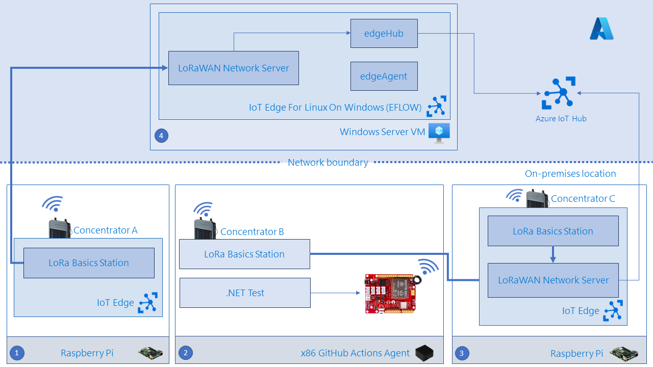
Given the need for real hardware, the setup must include a self-hosted GitHub Actions runner (marked with 2 in the picture above).
A single Seeeduino LoRaWAN leaf device (red device shown in Diagram 1) is connected via USB to the GitHub Actions Runner. This leaf device is used for each E2E test in order to impersonate a real LoRa sensor sending radio messages. Furthermore, it can be configured to support different radio and LoRa configurations.
When a leaf device is emitting a frame over the air, one or multiple concentrator devices are collecting and demodulating the radio waves. Each concentrator, running LoRa Basics Station (LBS) collects the radio frequency packets and forwards them to a specific LoRaWAN Network Server (LNS).
As seen in Diagram 1, the setup includes three concentrators:
- Concentrators A and C are connected via SPI (Serial Peripheral Interface) to Raspberry Pi devices (identified by numbers 1 and 3) and accessed through an IoT Edge installation running a containerized instance of LBS
- Concentrator B is connected via USB to the x86 GitHub Actions Agent (identified by number 2) and accessed through a process running an instance of LBS.
In the case of concentrator A, the correspondent LoRaWAN Network Server is located inside an Azure IoT Edge for Linux on Windows (EFLOW) installation in a Windows Server VM hosted on Azure. In the case of concentrators B and C, the correspondent LoRaWAN Network Server is located inside an IoT Edge module hosted on device 3.
A LoRaWAN Network Server receives the messages coming from one (or multiple) concentrator(s) and processes the information, sending the message to IoT Hub and eventually sending back a downlink packet for acknowledging the message or providing commands to the leaf device.
Leaf device configuration
The leaf device is setup with a serial pass-through sketch, allowing each .NET test to properly set it up.
When a test starts, it opens the serial port where the communication with the leaf device should happen and sends AT Commands to configure the device for communication.
As an example, in order to impersonate a device using ABP activation mode (Activation By Personalization), sending a single message, the following AT commands should be issued:
AT+FDEFAULT=RISINGHF
AT+MODE=LWABP
AT+ID=DevAddr,{DevAddr}
AT+ID=DevEui,{DevEUI}
AT+KEY=NWKSKEY,{NetworkSessionKey}
AT+KEY=APPSKEY,{AppSessionKey}
AT+MSG={Message}
A LoRaArduinoSerial C# Class has been written in order to provide helper methods that can easily interact with such AT commands and their return values. The return values from the LoRa modem are used for verifying and asserting if certain operations succeeded or not.
Thanks to this approach, each test has great flexibility in configuring a leaf device. Typically, this will involve configuring the activation mode for the device – ABP or OTAA (Over-The-Air Activation), the class of the device and which channels (frequencies) should be used by the device to broadcast uplink messages.
Concentrator and LoRaWAN Network Server configuration
A concentrator is collecting and demodulating the radio waves. LBS is being used to communicate with the concentrator (via SPI or USB) and forward the radio packets received to one LoRaWAN Network Server (LNS).
The communication between an LBS and its LNS is happening through TCP/IP, either using HTTPS (for CUPS protocol interactions) or using WebSockets (including WebSockets Secure) for LNS protocol interactions.
This is opening the way for testing several different scenarios:
| Concentrator | LoRa Basics Station host | LoRaWAN Network Server | Protocol | Additional comments |
| Concentrator “A” | IoT Edge module in Raspberry Pi (1) | IoT Edge module in EFLOW installation on Azure VM (4) | ws (LNS only) | A VPN connection between the CI Runner and the EFLOW VM is used |
| Concentrator “B” | “On-demand” standalone binary in GitHub Actions agent (2) | IoT Edge module in Raspberry Pi (3) | https+wss (CUPS and LNS) | Local network communication between the CI Runner and the AIO device. “On-demand” means that the test itself is starting the Basic Station with the desired configuration |
| Concentrator “C” | IoT Edge module in Raspberry Pi (3) | IoT Edge module in Raspberry Pi (3) | wss (LNS only) | Same device communication |
E2E test flow
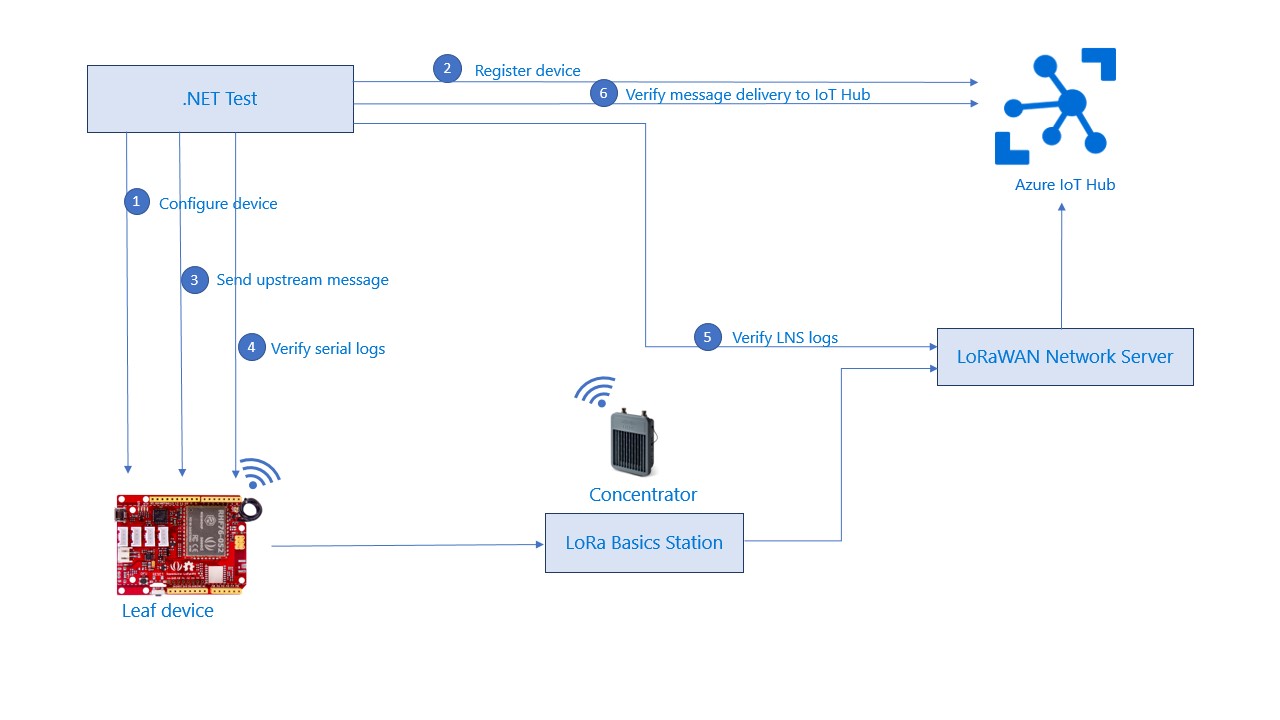
The diagram shown in Diagram 2 shows a typical flow of an E2E test in the LoRaWAN Starter Kit.
- The leaf device is configured from the test code with correct device ID, authentication mode, region and other settings.
- The device is registered in IoT Hub.
- The device broadcasts an upstream message which is picked up by the Concentrator. The message should then reach the Network Server and eventually be delivered to IoT Hub.
- The test verifies the serial logs of the leaf device.
- The test verifies the logs of the Network Server.
- The test verifies that message was delivered to IoT Hub.
Challenges in E2E testing
As described in more detail in the previous section, the solution was designed to offer a lot of flexibility in terms of deployment options for the different components and authentication modes. This posed the requirement for the E2E tests to be flexible enough to cover all possible deployment and authentication configurations. As an example of how this problem was addressed in the Starter Kit, the E2E tests of the project include tests specific to multi-concentrator setup as well as both a single-gateway and multi-gateway versions of certain E2E tests. The hardware setup of the E2E CI pipeline is flexible enough to support all these configurations.
Assertions in the E2E tests of the Starter Kit typically involve checks of the log outputs from specific components. This involves the logs of the Network Server, serial logs from the leaf device, and logs of the IoT Hub. The need to verify that expected messages are logged by these components during test runs was addressed in the project by making sure that logs from different components can be forwarded to the machine executing the E2E tests. We achieved this by allowing the user to configure the target IP address for the logs when deploying the solution.
Because many functionalities offered by the LoRaWAN protocol are time-sensitive and require adherence to specific time windows, we decided to introduce automatic test retries in the E2E setup. This helped us greatly reduce the number of failures related to transient radio or timing issues.
Open problems and limitations
Differences in regional specifications of the LoRaWAN protocol is one of the biggest challenges for E2E testing. Differences in implementation of regions in the project created the need for testing each of the regions supported by the Starter Kit.
Due to the frequency restrictions, it is only possible to test one region at a time. In particular, the E2E CI pipeline that has been set up for the Starter Kit project can only use the EU863 region specification of the protocol due to the local regulations of the geographical location.
However, the leaf devices used in the CI workflow could theoretically be programmed to use a different LoRa region, if this was allowed by local country regulations. In addition, the regional setup could be integrated by adding another concentrator device supporting different frequencies for a different region. The LBS configuration is flexible as it is simply a JSON structure inside a device twin fetched from IoT Hub. Therefore, different region Basic Stations can be connected to the same LoRaWAN Network Server instance at the same time without any issue.
The current E2E setup for the Starter Kit does not allow executing more than one E2E workflow at a time. As such, scaling the existing E2E setup would require additional agents and new sets of hardware.
The potential challenge of maintaining multiple hardware setups would be making sure that test runs on different environments do not interfere with each other. Achieving this would likely require physically isolating the devices and concentrators.
Acknowledgements
Contributors to the article from the Microsoft team listed in alphabetical order by last name: Atif Aziz, Bastian Burger, Mikhail Chatillon, Roel Fauconnier, Spyros Giannakakis, Daniele Antonio Maggio and Patrick Schuler.