

The core value proposition of the Fluid Framework is to provide distributed, eventually consistent state across multiple clients in a highly resilient, cost-effective manner with minimal latency. One of the important steps in achieving good latency is the optimal placement of the geographically distributed Azure Fluid Relay (AFR) servers and deciding how we would route the traffic to these servers. This blog explores how we route the traffic such that we minimize latency while adhering to the data residency and redundancy requirements for planned and unplanned outages.
Overview
Azure Fluid Relay consists of two services that can scale independently and have different compliance requirements.
Ordering Service:
- Function: Guarantees eventual consistency via total order broadcast. It assigns a monotonically increasing sequence number to all operations received from the client and broadcasts them back to the connected clients, which reconcile the operations to converge to a consistent state. The ordering service is optimized for minimizing latency.
- Compliance: Data flowing through the ordering service is considered data in motion and is periodically purged, so it is not subject to strict compliance requirements.
Storage Service:
- Function: Periodically persists the summaries of operations so that all operations don’t have to be replayed when a new Fluid client connects and loads a distributed data structure.
- Compliance: The data passing through the storage services is considered data at rest and is subject to data compliance requirements.
Since the ordering service and the storage services scale independently, we can reduce infrastructure and operational costs by deploying storage services (data at rest) in every region but deploying the ordering service (data in motion) only in select locations to optimize latency. We need the sequencing and broadcasting of the operations to be as fast as possible. Since we do not have data residency requirements for operations in transit, we can strategically choose to deploy the ordering services in fewer Azure regions. For the summaries, however, we need to follow the data residency requirements, necessitating one instance in every Azure geo.
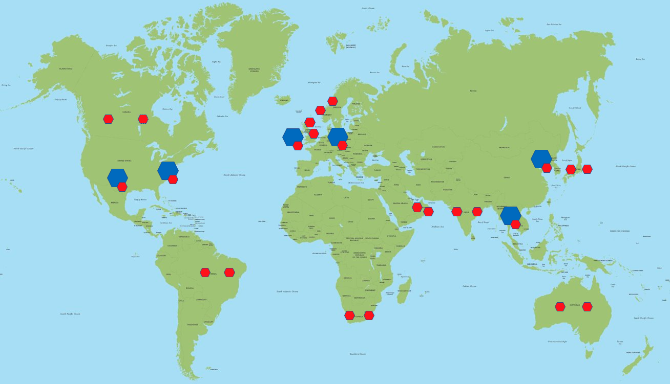 In the diagram above, blue components represent the ordering services (handling data in-transit), and red components represent the storage services (handling data at-rest).
Discovery process
In Azure Fluid Relay, the client connection process starts with a step called Endpoint Discovery, when a client accesses a specific URL (called the “discovery endpoint”) to get the location of the optimal ordering and storage services. Since Azure Fluid Relay is geographically distributed, this means that we need a global load balancer which sits in front of all the AFR clusters. We chose Azure Front Door (AFD) for the needs of AFR.
Azure front door is a global, scalable entry-point that uses the Microsoft global edge network. Front Door provides a range of traffic-routing methods and backend health monitoring options to suit different application needs and automatic failover scenarios.
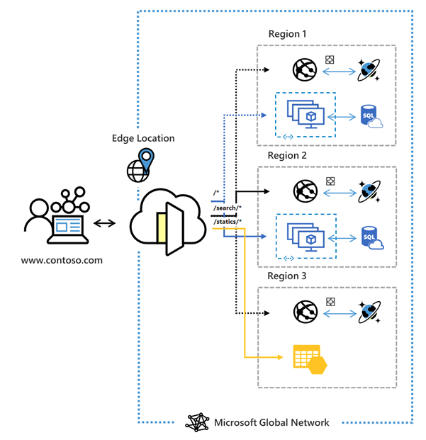 Figure 1: Azure Front Door architecture
The first HTTP call that the client makes gets routed to AFD and it will proxy the call to the optimal ordering service. AFD will ensure that the end users promptly connect to the nearest Front Door POP (Point of Presence) and then use the Microsoft global network to connect to the optimal AFR cluster. This will ensure significantly improved latency, security and reliability compared to the public internet. PoPs are strategically distributed across the globe and perform health checks on different AFR clusters to ensure they are operational. If a backend service is unhealthy, the PoP will stop routing traffic to it, ensuring only healthy backends receive traffic.
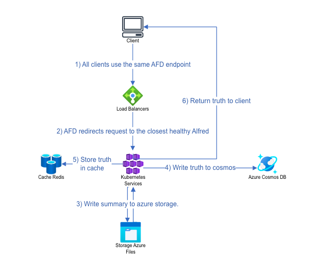
A Fluid container is the primary unit of data encapsulation in the Fluid Framework. It enables a group of clients to access the same set of shared objects and co-author changes on those objects. It also serves as a permission boundary, ensuring visibility and access only to authorized clients. During the container creation flow, AFD routes the creation request to the cluster closest in terms of latency and sends information about this cluster back to the client. If this cluster is down, AFD intelligently routes the request to the next closest healthy cluster. The diagram below shows the container creation flow:
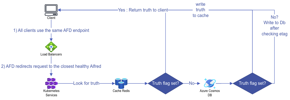
For the container join flow, AFD will still route the request to the closest cluster which will do a lookup to get the location of the collaboration session that is already active and send this information back to the client. The diagram below shows the join container flow:
Once the optimal cluster is selected to serve the session, any summaries generated will be stored in and retrieved from the user’s designated home location, which is specified during tenant creation. Operations are transmitted to the latency-optimized cluster, enabling extremely fast collaboration but the summaries may be stored in a distant location from the optimal cluster. This is because summary creation typically occurs in the background and is not part of the critical path in the total order broadcast process.
With AFD in place, AFR has redundancy at several levels all the way from a pod failure to the failure of a complete azure region. By leveraging Azure Front Door’s global network and the strategically placed PoPs, Azure Fluid Relay ensures minimal latency, high reliability, and compliance with data residency requirements.
Fluid Framework 2 is production-ready now! We’re excited to see all the collaborative experiences that you’ll build with it.
Visit the following resources to learn more:
- Get Started with Fluid Framework 2
- Sample app code using SharedTree DDS and SharePoint Embedded
- For questions or feedback, reach out via GitHub
- Connect directly with the Fluid team, we would love to hear what you are building!
- Follow @FluidFramework on X (Twitter) to stay updated
0 comments