
Rotary Wheel Control with HeavenFresh
Windows 10 introduces the Universal Windows Platform (UWP) providing a common app platform enabling the ability to install the same app package onto every Windows 10 device: phone, desktop, Xbox, IoT, Surface Hub, etc. We worked with @HeavenFresh to create a UWP application and, in the process, a rotary wheel user control. This case study describes the approach taken in building the resulting user control including the mechanics involved with drawing a rotary wheel, supporting user interaction, and the usage of storyboards for animations.
Customer Problem
HeavenFresh makes a plethora of products for the home including AllJoyn connected air purifiers and humidifers. In preparation for IFA Berlin 2015, we held a hackfest to build a Universal Windows Platform application to control HeavenFresh devices from a Windows 10 device. During this collaboration, we wanted to have a single user interaction element that could be used to configure different settings of the humidifier/purifier (e.g. fan speed, humidity level, etc). This led us to building a rotary wheel user control which allowed us to reuse the same component across the application.
Overview of the Solution
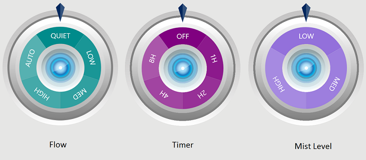
Shown below is the stylized rotary wheel control used in HeavenFresh’s application:
The same control was re-used across the application to configure different settings of the air humidifier and purifier.
Implementation
Given the labels, the user control creates the necessary number of equally-sized slices to build the wheel. Touch and mouse events are supported, and when the user completes manipulation of the wheel, the wheel animates back to the center of the selected slice.
The rotary wheel control can be broken down into the following components:
- Individual slice
- Collection of slices making a wheel
- User manipulation to rotate wheel
- Animation of centering to the selected slice
Slice
In its basic form, the rotary wheel is comprised of an arbitrary number of equally sized slices. Leveraging Jerry Nixon’s blog post, three arguments are required to build a slice:
StartAngle– start angle of the sliceAngle– total angle of the sliceRadius– radius of pie slice
In order to center the slice’s label in the middle of the slice, the label requires two render transformations:
- rotate – align the label with the angle of the slice
- translate – move the label to the center of the slice
The resulting XAML of the slice is shown below:
<Grid x:Name="layoutRoot">
    <!-- Slice Path (refer to Jerry Nixon post) -->
    <userControl:PieSlicePath x:Name="pieSlicePath" Canvas.ZIndex="1" />

    <!-- Label -->
    <TextBlock x:Name="textBlock" Canvas.ZIndex="2" Text="{Binding Label}" RenderTransformOrigin="0.5, 0.5">
        <TextBlock.RenderTransform>
            <TransformGroup>
                <RotateTransform x:Name="textBlockRotate" />
                <TranslateTransform x:Name="textBlockTranslate" />
            </TransformGroup>
        </TextBlock.RenderTransform>
    </TextBlock>
</Grid>
Rotate
Firstly, we configure the RenderTransformOrigin property of the textblock. RenderTransformOrigin accepts a value between 0 and 1 and indicates the origin point of the rotate transform. As we wish to rotate based off the center of the textblock, the property is set to RenderTransformOrigin="0.5, 0.5".
Given the total angle of the slice is Angle, to align the label with the slice, the rotate transform angle is StartAngle + Angle/2.
Translate
To appear centered in the middle of the slice, the label needs to be translated approximately 4/5 the slice radius.
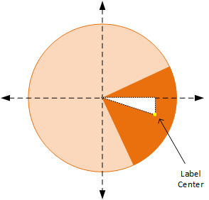
A closer look at the above diagram results in the following right-angle triangle:
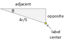
The sides of the triangle can be calculated through basic trigonometry.
// where quadrant is an enumeration
// NE = 0, SE = 1, SW = 2, NW = 4
var quadrantAngle = startAngle + angle/2 - 90*(int)quadrant;

var adjacent = Math.Cos(Math.PI/180* quadrantAngle) *radius;
var opposite = Math.Sin(Math.PI/180* quadrantAngle) *radius;
In the grid system, translations are relative to the top-left most point of the element (up = negative; down = positive; left = negative; right = positive). The below diagram displays the cartesian grid with (0,0) being the top-left most point of the element.
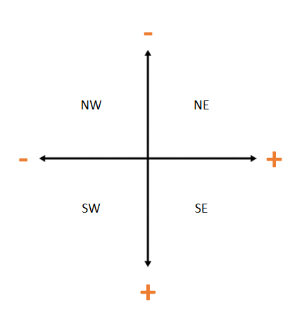
As such, depending on which quadrant the slice is in, the polarities of the X,Y translation will vary.
Wheel
The wheel is a collection of slices with differing StartAngle. The Angle of each slice remains constant and is calculated as 360/<total number of slices>.
var sliceLabels = new[] {'high', 'med', 'low'};
var sliceSize = 360/sliceLabels.Count();
foreach (var slice in sliceLabels)
{
    var pieSlice = new PieSlice
    {
        StartAngle = startAngle,
        Angle = sliceSize,
        ...
    };

    // add pie slice to canvas
    _pieSlices.Add(pieSlice);
    startAngle += sliceSize;
}
User Manipulation
In order to support user manipulation of the wheel, the parent grid housing the pie chart is given a rotate transform in which the Angle property will be updated during ManipulationDelta events. During the callback, the angle in which to rotate the wheel is calculated based on the touch point.
<StackPanel x:Name="layoutRoot"
            ManipulationMode="All"
            ManipulationDelta="layoutRoot_ManipulationDelta"
            ManipulationCompleted="layoutRoot_ManipulationCompleted">
    <Grid x:Name="layoutWheel">
        <!-- slices are programmatically added here -->

        <Grid.RenderTransform>
            <RotateTransform x:Name="gridRotateTransform" Angle="{Binding Angle}" />
        </Grid.RenderTransform>
    </Grid>
</StackPanel>
Animation
As an added effect, upon the completion of the user interaction, the wheel will rotate itself to the center of the selected slice. Animations are accomplished through Storyboards.
Our Storyboard will target the Angle property of the gridRotateTransform object. As the Angle property is of type Double, we apply a DoubleAnimation to transition the property between two Double values over a specified duration.
<UserControl.Resources>
    <Storyboard x:Name="storyBoard">
        <DoubleAnimation
            x:Name="doubleAnimation"
            Storyboard.TargetName="gridRotateTransform"
            Storyboard.TargetProperty="(Angle)"
            Duration="0:0:0.5"/>
        </Storyboard>
</UserControl.Resources>
When the user finishes manipulation of the control, a ManipulationCompleted event is fired. During the event callback, we determine:
- the selected slice
- the configured angle of said selected slice, and
- start the storyboard to rotate the pie chart to the center of the selected slice.
private void layoutRoot_ManipulationCompleted(object sender, ManipulationCompletedRoutedEventArgs e)
{
    var angleFromYAxis = 360 - Angle;
    SelectedItem = _pieSlices.SingleOrDefault(p => p.StartAngle <= angleFromYAxis && (p.StartAngle + p.Angle) > angleFromYAxis);

    var finalAngle = SelectedItem.StartAngle + SelectedItem.Angle / 2;

    doubleAnimation.From = Angle;
    doubleAnimation.To = 360 - finalAngle;
    storyBoard.Begin();

    Angle = 360 - finalAngle;
}
Challenges
With UWP and its ability to deploy to various devices, developing a user interface element for varying form factors and differing viewing options is difficult. As such, emphasis was placed on using responsive layouts such as stack panels and hard-coded sizing of control widths/lengths was refrained from.
Opportunities for Reuse
The rotary wheel user control is published on GitHub and can be used for any UWP application. Additionally, the described approach of leveraging render transformations, manipulation events, and storyboards is applicable when building your own user control.
 Light
Light Dark
Dark
0 comments